Suspension Technology

ARTICLES ON THIS PAGE
  • HOW TO SET RACE SAG
  • BASIC VALVING EXPLAINED
  • SHOWA SEPARATE FUNCTION AIR CHAMBER TUNING
  • MOTORCYCLE FRONT END TRAIL EXPLAINED      
          Hidden Effect of Motorcycle Trail
  • HOW ENGINE TORQUE AFFECTS THE SUSPENSION

HOW TO SET RACE SAG


First measurement is made with the Bike ON THE STAND

Second measurement is made with the bike OFF THE STAND and WITH RIDER STANDING ON THE PEGS


The DIFFERENCE of the two measurements = RACE SAG
Race Sag is generally set between 100 and 110 mm
Use the Spring Preload adjuster to adjust your Race Sag
BASIC VALVING EXPLAINED

BASIC VALVING EXPLAINED

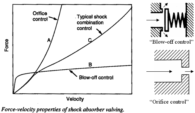
Suspension Tuners use 'Valving & Orifice' Adjustments to configure the Shaft VELOCITY Vs Damping FORCE Curve in a shock or Fork

A simple orifice “valve” generates a damping force which is progressive as shown in curve A.  If a tuner chooses a small enough orifice to control low speed suspension movements, the suspension would become too stiff and spike the rider on high speed (square edge) bumps. So another circuit must be added.

Valves covering piston openings (orifices) generate damping forces as shown in curve B. The valves remain closed until increasing shaft speeds cause enough pressure at the valves to “blow-open” and flow. In a true Blow Off design, after initial opening, pressures rise slowly with increases in velocity as shown in curve B.  These two types of “valving” complement each other since their damping characteristics are inverse.  A good suspension tuner can achieve a typical overall damping curve like C. 

Blow Off curve B can be further refined by adding additional valves behind the Blow Off valves. These additional valves can cause an upward curve to line B and thus further fine tune Total Curve C.

The final objective is enough low speed control for handling without creating harsh action in sharp or successive bumps.​​​​​​​

Rick Johnson

Too Tech Racing

SHOWA SEPARATE FUNCTION AIR CHAMBER TUNING

This graph (courtesy of Showa) Illustrates how the Air Spring Cartridge combines 3 air Chambers to create a 'Spring Like' Fork using compressed air. This Separate Function Fork is unique in that the rider can custom tailor any spring curve including curves that can't be created using an actual spring.
  • It is actually a very creative design on paper.
  • It does suffer from a lack of understanding by the general public
  • It also suffers from the need to seal the various chambers with additional seals which unfortunately add stiction to fork action. Stiction is the worst feature a fork can have!
Notice the 'Inner Chamber' and 'outer chamber' both add a force to hold the bike up like a spring. Examine the 2 curves to see that they add force at different fork displacements. Adding these 2 curves together create a unique "spring Like" force. Unfortunately, this force is far too high at fork extension (shown as 0 on the X axis) This force must be knocked down to almost zero at full extension, THUS the need for a 'Negative Force' or 'Balance Chamber' force that is strongest at full extention (0 on the x axis). Then as the fork compresses, this Balance Chamber force needs to disapear and allow the 2 "spring like" forces to take over.
Study the 3 air chamber contributions to Total Force and you will see how they combine to make a wide variety of spring like combinations.

Rick Johnson Too Tech Racing
Motorcycle Front End "Trail" Explained
Hidden Effect of Motorcycle Trail
 “Trail” determines the amount of self-straightening a vehicle has. A good hands-on illustration of trail is noted when pushing a shopping cart. As you push it forward, the wheel will always follow the steering axis. The tendency to follow the steering axis makes the wheel stable and follow behind the steering axis. As the wheel follows behind the steering axis it points forward. Without trail you could not take your hands off the wheel (without crashing that is)

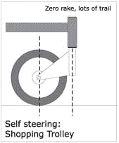
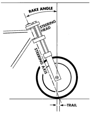
“Trail” is the distance at ground level between a vertical line intersecting the front axle and a line drawn from the headstock Center Line to the ground along the steering axis angle. Stable handling demands that the line through the headstock contacts the ground in front of the vertical line dropped from the wheel axle. ​​​​​​​

Note: Changing Tripple Clamp Offset changes the distance between the Steering Axis and the Steering Head Axis which changes the wheelbase, adds or subtracts weight from the front wheel, and changes the trail dimension.IT DOES NOT change the Front End Rake Angle !

CLASSICAL DEFINITION OF TRAIL AFFECTS

Trail affects front-end stability and the ease with which the bike steers. The longer the Trail distance, the more stable the bike is. This is because the farther behind the steering axis the wheel sits, the more likely the wheel will follow directly behind the steering axis and point forward – thus stability. The only ‘classical definition’ tradeoff to "large" Trail dimensions is that the steering requires more effort and more rotation of the handlebars to initiate a turn. Conversely, a shorter Trail distance creates lighter & quicker steering but less self straightening effect.

THE CLASSICAL DEFINITION MISSES THE INFLUENCE OF LEAN ANGLES AND BUMPS

I cannot find a description that includes how trail affects handling in the bumps and lean angles that we encounter off road or on MX tracks. The closest I came to someone insinuating another affect is below:

“A higher mechanical trail is known to make a bicycle easier to ride "no hands" and thus more subjectively stable, but skilled and alert riders may have more path control if the mechanical trail is lower”.

My explanation goes as follows:

We know that the tire contacts the ground directly behind where the steering axis intersects the ground. When the bike is upright, the tire is behind the steering axis and wants to stay behind (like a shopping cart). The weight of the bike is directed downward (vertical) and reacted by the ground which pushes directly upwards. This upward vertical force is directly in line (parallel) with the steering axis, so there is no turning force imparted to the forks. When hitting bumps with the bike straight up and down, the instantaneous load increase comes directly upwards through, and parallel with, the forks and does not create any turning moments.

HOWEVER, when we lean the bike over things change! Imagine the bike leaned over until the pegs almost touch the ground. The weight of the bike is still directed straight down at the tire contact patch, and the ground still pushes directly up at the same point. BUT this time the forks axis is not in line with the upwards force, but instead the upward force is ‘sideways’ (almost perpendicular) to the forks. Since this sideways force is behind the steering axis, it uses the Trail distance as a lever arm to rotate the forks around the steering axis. SO; the larger the trail dimension, the longer the lever arm available to create this “SELF STEERING” rotational force as the bike leans over. Now on a street bike driven on a flat road, this self-steering force is steady and predictably increases as the bike leans over further, so increased trail does not create a handling problem. Larger trail dimensions do require slightly more rider strength, but with no bumps the effects are calm and predictable.

BUT on a dirt bike the results are dramatically different when we lean the bike over and hit bumps. When we hit bumps, we momentarily load the tires far more than the weight of the bike (illustrated by pinched tubes on square edges). This instantaneous additional load at the tire is reacted by the ground and pushes back at the tire contact patch with an equally large force. SO; when we are leaned over AND hit a sharp bump, the instantaneous load at the tire goes up creating an instantaneous and unexpected ‘self-steering’ effect. The more we lean over and the sharper the bump, the more violent the self steering force becomes. Additionally, the longer the “Trail” dimension, the longer the lever arm and the more violent the ‘self-steering’ event becomes. And of course, all this instantaneous and unexpected self steering comes when we are leaned over and the most vulnerable to any steering disturbances. 

ADDITIONALLY, this self-steering effect is noticed in rough choppy terrain even when the bike is straight up. Don’t try this: but imagine driving straight at a 3” curb (so the curb is perpendicular to the bikes motion). When the tire contacts the curb, the load is inputted behind the steering axis and directly up parallel to the forks so there is no tendency to rotate the forks. But imagine if you drove at a 45-degree angle at the same curb. The impact force would come in behind the steering axis, but the force would be at a 45-degree angle. The sideways component of this force would act over the trail dimension’s ‘lever arm’ and cause a large steering input. Unfortunately, our bumps follow no particular pattern and are seldom perfectly perpendicular, so self-steering effects are inevitable. Although it is difficult to characterize exactly how a rough, sharp edged, angled bump, whooped out downhill is affected by trail, it is safe to assume that larger trail dimensions impose greater self-steering. And these effects increase as the track gets rougher.

Since “Trail” is designed into the bike’s geometry, we can only make small changes to it by altering the race sag or fork height. Interestingly, as Honda increased trail on the 2008 & 2009 Honda’s, they also installed a steering damper to minimize the effects of self-steering’. Unfortunately, Honda did not put enough damping into the steering damper to handle these forces but conceptually it was a reasonable approach. Too Tech can modify the Honda damper to better control impact related self-steering. And the damper can be attached to current Front end using existing drilled holes.

Incidently, as fork tube diameters have increased (Showa is using 49mm lower tubes), front ends have become stiffer. Thus, the impact forces and self-steering forces have also increased. I believe this has driven the push to softer (more compliant) modern dirt bike frame designs. The industry and public are beginning to understand that increased frame compliance and reduced impact compression damping are the best solutions to harsh self-steering inputs. Too Tech can’t redesign your frame, but carefully reducing impact compression damping will minimize self-steering forces.

Too Tech prides itself in relaxing damping as much as possible to minimize front end twitch...

Rick Johnson   Too Tech Racing

HOW ENGINE TORQUE AFFECTS THE SUSPENSION


BACKGROUND

                There seems to be a lot of confusion regarding how tension in the chain affects a motorcycle suspension.  Contrary to many track side opinions, the tension in the chain during acceleration does not cause the rear end to sag, but instead, actually reduces the frame’s tendency to squat.  To prove this, perform this simple experiment:  Put your bike in 1st gear directly in front of some immovable object such as a tree.  Rev up the motor and slowly let out the clutch loading the motor.  Notice how the rear fender rises under this load. This is caused by chain tension applied at an angle to your swing arm!

                The net squat that one sees between the rear wheel and the fender during acceleration is caused from the vehicle’s weight being transferred to the rear wheel under acceleration and the rear spring deflecting under this increased load.  The chain tension force is actually trying to raise the rear end!

                Riders use chain tension to their advantage.  For instance, if you gas it as you go up a jump ramp the bike will fly higher and farther.  If you chop the gas as you go off a jump, the bike will stay lower and not go as high or far in the air.  This is all because of tension in the chain.  Read on for the technical explanation of chain tension and how it affects bike action.

                What effects I will explain: To better understand the effects of chain tension, we will look at the forces the chain exerts on the rear wheel and frame, how these forces affect suspension performance, and then discuss how the rider can use these forces to his advantage on the track.  Then we will discuss the pros and cons of the ‘Torque Eliminator” product’s ability to eliminate these chain reactions.  We will choose some numbers for engine torque, bike & rider weight, and calculate the approximate lifting force generated by the tension in the chain.  We will ignore some other forces acting during acceleration so we can focus on chain tension and the associated lifting forces.  This is not completely accurate, but close enough to make the point of this analysis. 

                Sketch Explanations:  Straight lines with arrows indicate forces and their direction of application.  Circular lines indicate torque with the arrow showing the direction of application.  The numbers indicate magnitude.  To understand the effects of a force (straight arrows) drawn at some angle other than vertical or horizontal, we “resolve” the angled force into its horizontal and vertical components.  In our example, ‘X’ will indicate horizontal and ‘Y’ will indicate vertical forces.  All forces must balance at some equilibrium force condition.  When we twist the throttle, the tension in the chain is added to the force equilibrium analysis.  This added force causes a new equilibrium condition and a short-term vertical acceleration (rear end lift) to get to this new point

CHAIN TENSION CALCULATIONS AND HOW THEY AFFECT THE FRAME  

                We will assume a total weight of 400 lbs for bike and rider.  We will look at suspension reactions with all the weight shifted to the rear wheel modeling maximum acceleration.  We will place the rear swing arm in the horizontal position to keep things simple. 

                First we must approximate the tension in the chain.  To accelerate, the engine produces torque at the drive sprocket; which applies tension to the chain; which then drives the rear sprocket.  We will choose a 250cc engine that produces about 25 ft/lbs of torque.  The second gear ratio is about 2 to 1 and the primary reduction ratio is about 2.5 to 1.  Total engine torque multiplication in second gear equals 5 to 1; thus drive sprocket torque is 125 ft/lbs (25x5=125).  For any torque, the force exerted is dependent on the leverage arm length.  In our example the front sprocket diameter is 3.5”.  The radius is 1.75” or .145 ft.  Dividing 125ft/lb of torque by the front sprocket radius of .145ft. yields approximately 850 lbs of potential chain tension (125/.145 = 850).  Since the rear tire typically slips in second gear, it is apparent that tire traction cannot contain all the available engine torque.  The engine starts to ‘free wheel’ at some point below its maximum torque potential, thus the tension in the chain doesn’t reach its full potential.  Tire slippage is dependent on terrain and rider technique.  A reasonable ‘SWAG’ (scientific wild ass guess) for actual chain tension in 700 lbs.  We’ll use this number for our analysis.


Note Sketch ‘A’.  In this sketch we first see a diagram of the two sprockets with a chain drawn between them.  Given a front sprocket of 1.75" radius and a rear sprocket of 5" radius, the actual rise (vertical component) along the swing arm axis is 3.25”.


​​​​​​​Note Sketch ‘B’.  The second diagram resolves the chain angle into X and Y components (distances) so we can calculate the angle of the chain.  The angle calculates to 8 degrees thus the 700 lbs of chain tension is at an 8-degree angle with respect to the horizontal swing arm.

Note Sketch ‘C’.  To determine the effects of 700 lbs of chain tension at the rear wheel and at the frame, we must resolve the chain tension into its perpendicular components with respects to the swing arm.  Note from our example that given the 8 degree angle determined above, the horizontal force ‘Fx’ calculates to 693 lbs.  The vertical force ‘Fy’ calculates to 100 lbs.

Note Sketch ‘D’.  This sketch shows the forces acting on the rear wheel and the frame that hold the system in equilibrium.  First note the horizontal force labeled Fx at the rear wheel.  The final result of the -693# force is to accelerate the motorcycle! In this diagram, the horizontal forces FX and FX1are held in equilibrium by combining to compress the swing arm some negligible amount.  

 The vertical forces are much more interesting AND the purpose of this analysis.  The Fy force acts at the rear wheel pushing it down, and its associated equilibrium force Fy1 is applied at the frame pushing it up.  In a standard ‘rigid body’ analysis, Fy1 and Fy would combine to form a ‘couple’, or torque, which would exert a torque or rotatioal force on the entire bike.  HOWEVER in our case, the swing arm is attached with bearings at both ends, so our two vertical forces are separated by a pivoting link system.  This link allows the two opposite vertical forces to cause vertical displacement instead of a torque.  The rear wheel Fy tries to make the tire go down in the rear.  The ground prevents this motion.  The opposite vertical force at the front sprocket Fy1 tends to lift the frame, which unloads the rear shock spring.  In our example this force is calculated to be 100 #. By applying 100 lbs of lifting force directly to the frame at the sprocket, the rear spring is relieved of 100 of the total 400 lbs of rider and bike weight.  This causes the bike to rise as if the rider suddenly lost 100 pounds.

                Out on the track, they forces are constantly at work. When the throttle is applied sudenly, chain tension occurs instantly causing the bike to try to lift as if the rider had suddenly lost 100 lbs.  This sudden loss of a 100-pound load from the rear spring causes the bike to accelerate upward to its new equilibrium point AND drive the rear tire harder into the dirt as if the bike suddenly gained 100 pounds of weight and instantaneously more grip to the dirt. Conversely, when the throttle is suddenly 'chopped off', chain tension applied to the chain below the swing arm tends to lower the bike and can be used to reduce lift off of a jump or keep the rear end down in the whoops, etc.

DISCUSSION AND APPLICATION  

                Remember, we chose 400 lbs for the total bike weight and we said all the weight would be transferred to the rear wheel during acceleration.  Without chain tension forces, all 400 lbs is transferred to the rear wheel through the rear shock spring.  When we consider the chain tension and analyze the resulting vertical forces at the rear wheel and frame, we realize that 100 of the 400 lbs of bike weight is applied directly to the rear wheel via the tension in the chain.  The remaining 300 lbs are supported by the rear shock spring. 

                The advantage of the conventional chain layout is the rider’s ability to use this upwards force to his advantage for pre-jumping obstacles and clearing double jumps.  As discussed earlier, this 100 lbs upward force reduces the weight carried by the spring and instead is supported by tension of the chain..  When you relieve the spring of part of its load, it accelerates upwards to a new equilibrium position.  When the rider coordinates this upward frame acceleration with a jump takeoff, the result is more upward motion and more distance.  Chain tension also tends to reduce bottoming when landing from large jumps.  Landing with the throttle on reduces suspension bottoming because the shock spring only has to support the impact forces from 300 lbs rather than the 400 lbs combined weight of the bike and rider.  This is why it important to touch the throttle when landing from jumps. Slight throttle application reduces the compression motion during landings and minimizes the up and down motion that prevents an immediate return to agressive riding.   

                 The disadvantage of the traditional chain alignment is that 100 lbs of the bike weight is carried by the “rigid” chain connection between the frame and rear wheel, thus the rear wheel behaves as if it had 100 extra pounds of ‘unsprung’ weight during acceleration.  Any ‘unsprung’ weight has trouble following the changes in terrain.  Adding another 100 lbs to this ‘unsprung’ weight during acceleration adversely affects the rear tire’s ability to follow the terrain. Additionally, if a rider fans the clutch or applies power in a non smooth ' on - off - on' manner, the frame tends to rise and lower causing loss of traction and acceleration. (This adds another reason to exit a turn one gear higher.  The higher the gear, the less the engine torque is multiplies; thus, the rigid connection between the frame and rear wheel is minimized!) 

               Rick Note: This was written years ago when the "torque eliminator product was being tested by many different publications.

 Note that the ‘Torque Eliminator’ system eliminates these forces so the rider cannot ‘dial in’ frame lift or anti-bottoming with the throttle.   By aligning the chain parallel to the swing arm, the chain tension becomes parallel to the swing arm.  Without an angle between the chain and the swing arm, the forces are purely horizontal with no vertical components.  No vertical forces means no frame lift and no rigid connection between the frame and rear wheel.  All 400 lbs of bike and rider weight act as ‘sprung’ weight transmitted to the ground through the rear shock spring.  This also explains why the ‘Torque Eliminator’ product requires a stiffer shock spring.  Without the 100 lbs vertical force at the frame to counter rear end squat during acceleration, the bike requires a stiffer spring rate to eliminate excessive squat.  Most riders experimenting with this ‘Torque Eliminator’ system found that they preferred the potential for frame lift over a smoother ride and this product lost favor. 

                It should be noted that a 500 cc bike has about 1.5 times more torque than a 250 cc bike and proportionally greater chain tension.  Conversely a 125 cc bike would have about half the potential chain tension of a 250 cc bike.   Additionally, there is more engine torque multiplication / chain tension in the lower gears and less in the higher gears.  This explains why reactions at the rear wheel and frame will be more noticeable in the lower gears with large displacement bikes. 

                Happy trails and don’t forget to ‘Gas It’ to clear that next obstacle or double jump!

By: Rick Johnson

​​​​​​​Too Tech Racing